
If you are learning electronics, one of the first and most important topics you will encounter is series circuits and parallel circuits.
Almost every electronic device around you uses one of these two circuit types—or a combination of both.
In this article, we will clearly explain the difference between series and parallel circuits using simple language, real-world examples, and easy comparisons. No confusing theory, no heavy math.
By the end, you will know:
- What a series circuit is
- What a parallel circuit is
- How current and voltage behave in each
- Where each type is used in real life
What Is a Series Circuit?
A series circuit is a circuit where all components are connected in a single path.
This means:
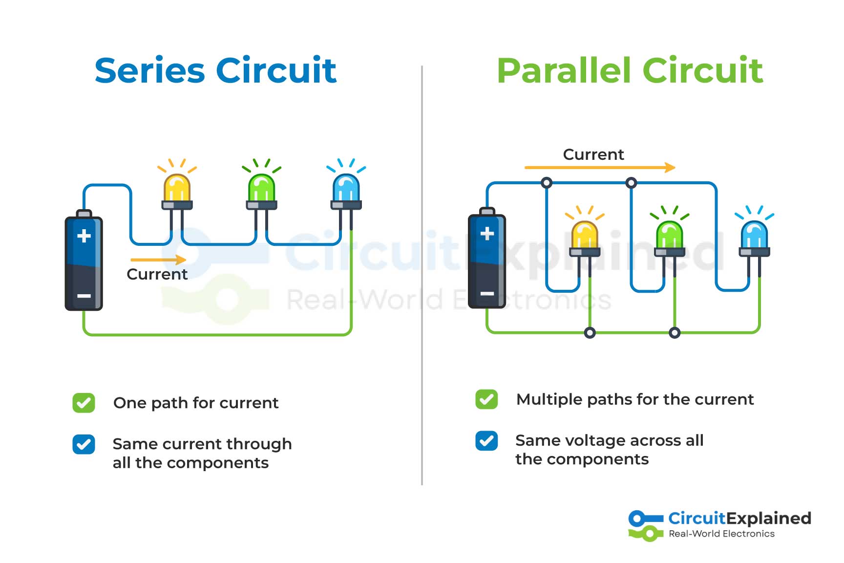
- There is only one path for current to flow
- The same current flows through every component
How a Series Circuit Works
If you connect a battery, a resistor, and an LED in a single loop, the current must pass through each component one after another.
If one component breaks or is removed, the circuit becomes open, and everything stops working.
Key Characteristics of Series Circuits
- Only one path for current
- Same current flows through all components
- Voltage is divided across components
- If one component fails, entire circuit stops
Real-World Example
- Old-style Christmas lights
If one bulb burns out, all the lights go off.
What Is a Parallel Circuit?
A parallel circuit is a circuit where components are connected across multiple paths.
This means:
- Current has more than one path to flow
- Each component receives the same voltage
How a Parallel Circuit Works
In a parallel circuit, each load (like a bulb or device) is connected directly to the power source.
If one path fails, the other paths continue working normally.
Key Characteristics of Parallel Circuits
- Multiple paths for current
- Same voltage across each branch
- Current is divided among branches
- One component failing does not affect others
Real-World Example
- Home electrical wiring
If one appliance stops working, others continue to operate.
Series vs Parallel Circuit: Side-by-Side Comparison
| Feature | Series Circuit | Parallel Circuit |
| Current Path | One path | Multiple paths |
| Current | Same everywhere | Divided |
| Voltage | Divided | Same across loads |
| Reliability | Low | High |
| Failure Effect | Entire circuit stops | Only one branch affected |
| Common Use | Simple devices | Homes, electronics |
Which Circuit Is Better?
There is no single “better” circuit. It depends on the application.
Use a Series Circuit When:
- Circuit needs to be simple
- Same current is required everywhere
- Low cost and fewer wires are important
Use a Parallel Circuit When:
- Devices must work independently
- Reliability is important
- Same voltage is required across loads
Most real electronic systems use a combination of both series and parallel circuits.
Common Beginner Mistakes
- Thinking current is the same in parallel circuits
- Forgetting that voltage divides in series circuits
- Wiring LEDs in series without proper resistor calculation
- Assuming household wiring is series (it is parallel)
Understanding these basics will help you avoid burned components and non-working circuits.
Simple Summary
- Series Circuit: One path, same current, voltage divided
- Parallel Circuit: Multiple paths, same voltage, current divided
If you are just starting out, build both types on a breadboard. Seeing them in action makes everything clearer.
What’s Next?
To go deeper, check out these upcoming guides on CircuitExplained.com:
- Ohm’s Law Explained Using Real Circuits
- How to Calculate Resistors for LEDs
- Series and Parallel Resistors Explained