


When you start learning electronics, one of the first questions you’ll face is: How do I calculate resistance when multiple resistors are connected together?
In real circuits, resistors are rarely used alone. They are connected in series, parallel, or a combination of both. Understanding how total resistance works is essential for circuit design, troubleshooting, and safety.
In this learning, I’ll explain series and parallel resistance in a simple, with clear formulas, diagrams, and examples. At the end, I’ll also show you how you can save time using my Series & Parallel Resistance Calculator.
What Electrical Resistance tells us?
Electrical resistance (measured in ohms, Ω) tells us how much a component resists the flow of electric current. A higher resistance means less current flows for a given voltage.
The total resistance of a circuit depends on how resistors are connected, not just their individual values.
Resistance in a Series Circuit
What Is a Series Circuit?
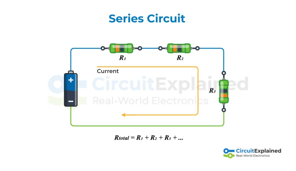
In a series circuit, resistors are connected one after another, forming a single path for current. The same current flows through every resistor.
Series Circuit Diagram
Formula for Series Resistance
When resistors are in series, the total resistance is simply the sum of all resistors:

Suppose you have three resistors:
- R₁ = 10 Ω
- R₂ = 20 Ω
- R₃ = 30 Ω
Total resistance:

Key Points About Series Circuits
- Total resistance increases as more resistors are added
- Current is same through all resistors
- A break in one resistor stops current everywhere and break the circuit.
Resistance in a Parallel Circuit
What Is a Parallel Circuit?
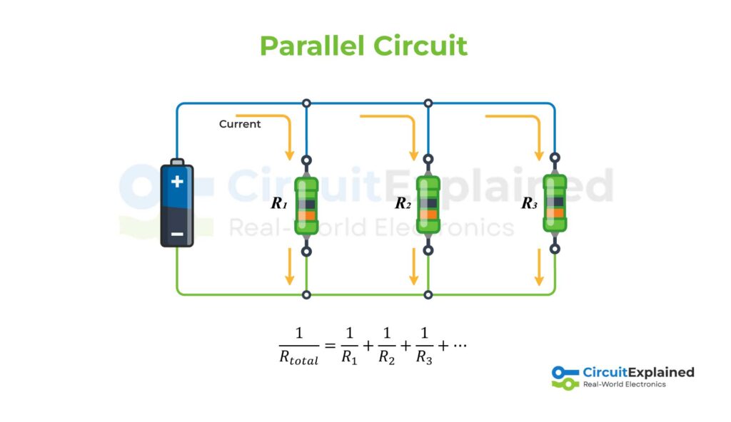
In a parallel circuit, resistors are connected across the same two points, creating multiple paths for current. The voltage across each resistor is the same.
Parallel Circuit Diagram
Formula for Parallel Resistance
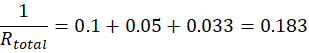
For parallel resistors, we add the reciprocals:
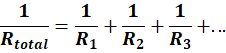
After calculating the sum, take the reciprocal to find Rtotal.
Example (Parallel Circuit)
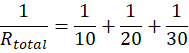
Using the same resistors values:
- R₁ = 10 Ω
- R₂ = 20 Ω
- R₃ = 30 Ω

Key Points About Parallel Circuits
- Total resistance is always less than the smallest resistor
- Current splits between branches
- If one branch fails, others can still work
Series vs Parallel Resistance (Quick Comparison)
| Feature | Series Circuit | Parallel Circuit |
| Total resistance | Increases | Decreases |
| Current | Same everywhere | Divides among branches |
| Voltage | Divides | Same across branches |
| Common use | Current limiting | Power distribution |
Why These Calculations Matter
Knowing how to calculate resistance helps you:
- Design safe electronic circuits
- Choose correct resistor values
- Prevent overheating and component damage
- Understand real-world wiring and PCB layouts
But let’s be honest, manual calculations can become slow when you’re designing the circuits, especially when you have many resistors.
Series & Parallel Resistance Calculator
To make things easier you can use any calculator available online, We’ve also built a Series and Parallel Resistance Calculator right here on Circuit Explained.
With this calculator, you can:
- Instantly calculate total resistance
- Switch between series and parallel modes
- Avoid calculation mistakes
- Save time during circuit design
Try the calculator below and verify your results in seconds.
Final Thoughts
Series and parallel resistance calculations are a fundamental part of electronics. Once you understand the logic behind them, circuit analysis becomes much simpler. If you’re learning electronics, experimenting with resistor values using a calculator is one of the best ways to build intuition.
If you found this guide helpful, feel free to explore more tutorials and tools on circuitexplained.com.
Happy learning