

If you’re just starting with electronics, a circuit diagram (also called a schematic) can look scary at first. Lines go everywhere, symbols look strange, many texts on a single components, and nothing resembles real components.
Reading circuit diagrams is a basic skill anyone can learn. I’ll explain it step by step and guide you, so you can learn easily.
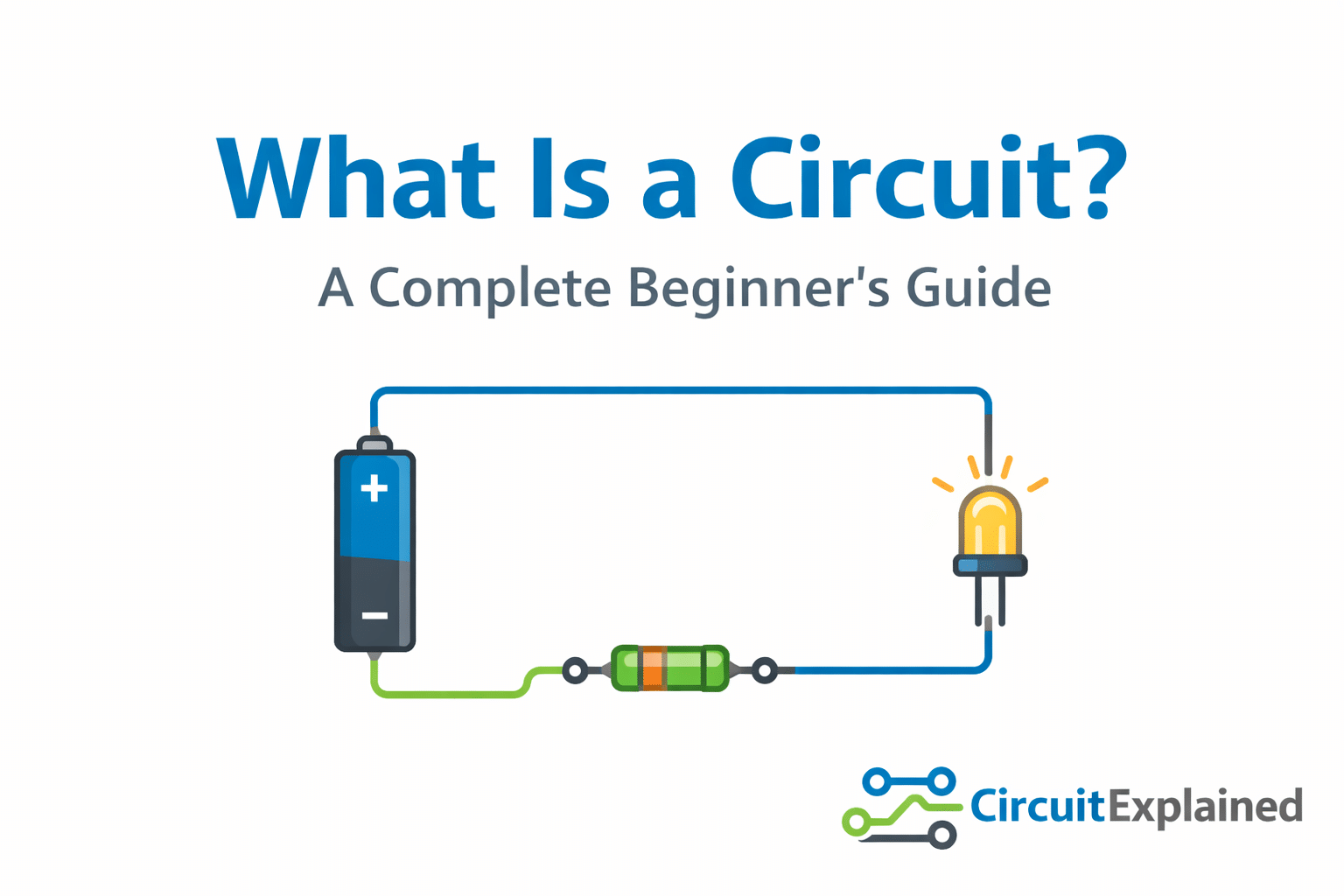
What Is a Circuit Diagram?
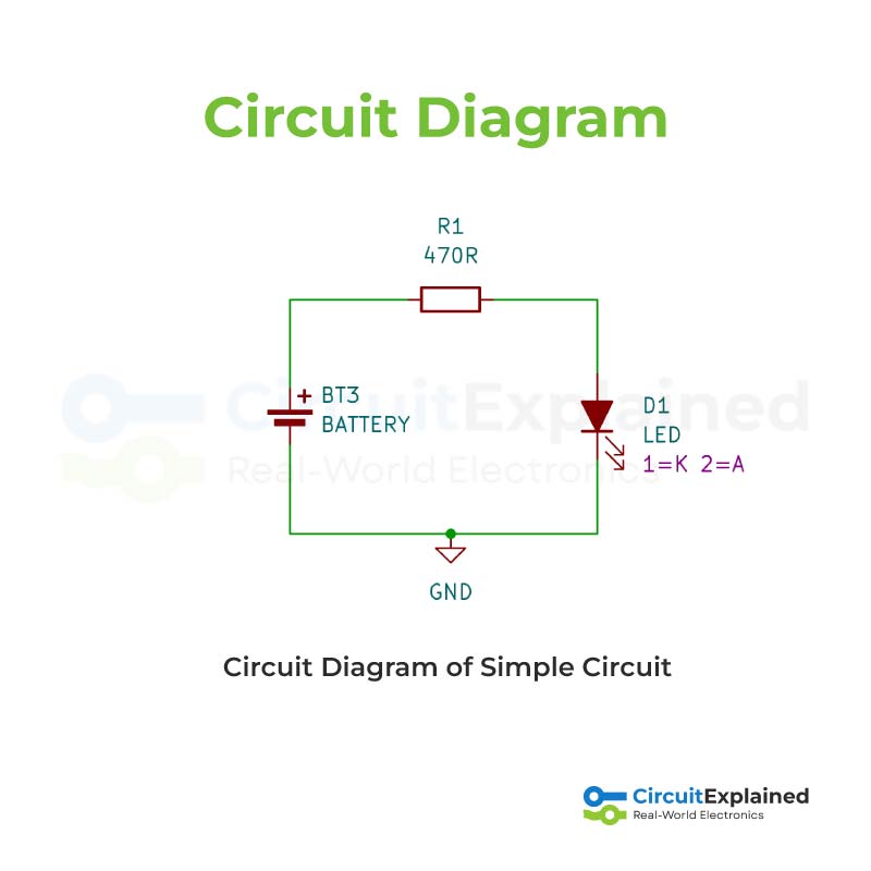
A circuit diagram is a drawing that shows how electronic components are electrically connected, not how they physically look.
It answers three simple questions:
- Where does power come from?
- Which components are used?
- How does current flow through them?
Engineers, hobbyists, and technicians use schematics to design, build, and troubleshoot circuits.
Suggest Reading:
What is Symbols in electronics and why they are used.
An electrical symbol is a small drawing or icon used in circuit diagrams to represent an electrical or electronic component.
Instead of drawing the real physical part, engineers use symbols to make circuits simple, clear, and easy to understand.
Common Circuit Symbols You Must Know
Before reading any circuit, learn these common symbols:

- Battery / Power Supply – Provides voltage
- Resistor – Limits current
- Capacitor – Stores electrical charge
- LED – Emits light when current flows
- Switch – Opens or closes the circuit
- Ground (GND) – Reference point (0V)
You don’t need to memorize everything at once. Start with the basics — most beginner circuits reuse the same symbols.
Follow the Flow of Current
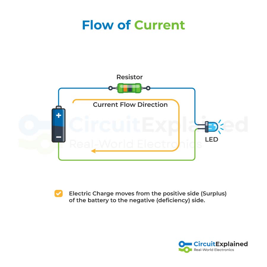
A very important rule:
Current always flows in a closed loop
Usually, current flows:
Power source → components → ground (or negative terminal)
When reading a circuit:
- Start at the battery or power source
- Follow the lines (wires)
- Go through each component one by one
- Return to the source
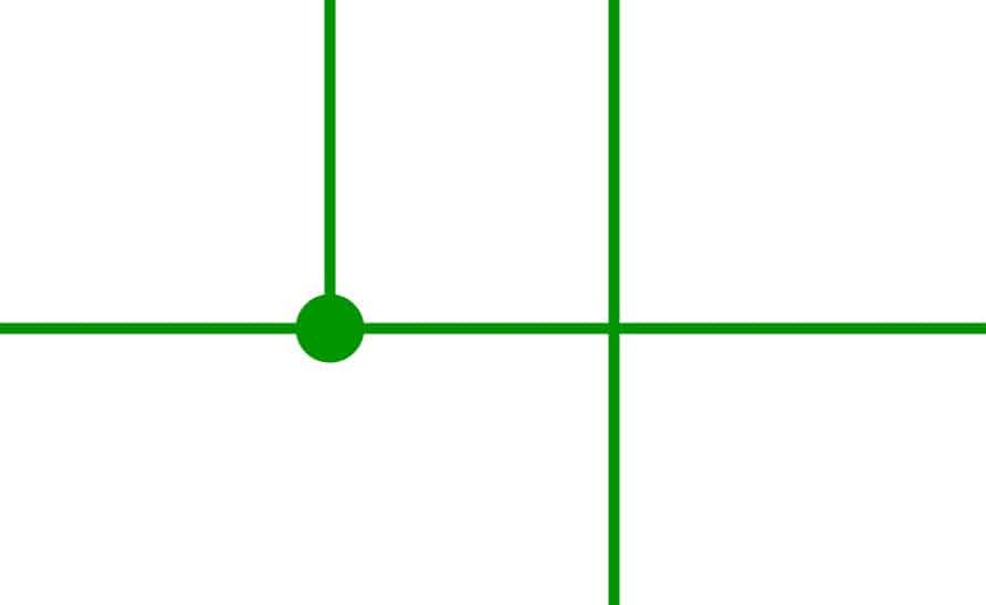
Lines represent wires.
A dot means connected.
Lines crossing without a dot are not connected.
Understanding Series and Parallel Connections


Most circuits use series, parallel, or a mix of both.
Series
- One path for current
- Same current through all components
- Used for current limiting and voltage division
Parallel
- Multiple paths for current
- Same voltage across components
- Used when components must work independently
Recognizing these patterns helps you quickly understand how a circuit behaves.
Suggest Reading:
Reading Component Labels and Values
Component names in a circuit diagram are made using letters and numbers.
The letter tells you what type of component it is, and the number helps identify it.
For example:
- R is used for resistors (R1, R2, R3)
- C is used for capacitors (C1, C2)
- U is used for integrated circuits or chips (U1, U2)
Each component in a schematic has a unique name, even if several components are the same type. This makes it easy to talk about, test, or troubleshoot a specific part in the circuit.
In simple words, component names help us quickly find and refer to exact parts in a circuit diagram.
and component values tell us how much or how strong a component is.
They are written next to the component name in a circuit diagram.
For example:
- A resistor may have a value like 1kΩ or 10Ω
- A capacitor may have a value like 10µF or 100nF
- A voltage source may be labeled 5V or 12V
The value helps us understand how the component will behave in the circuit.
Two components can have the same name type (like resistors) but different values, which means they will work differently.
Always read these carefully, they control how the circuit works.
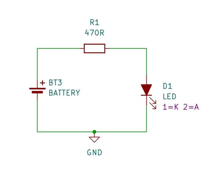
Start with Simple Circuits
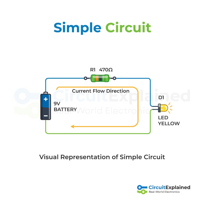
Beginner-friendly circuits include:
- Battery + resistor + LED
- Switch-controlled LED
- Simple sensor circuits
The more diagrams you read, the easier it becomes.
Reading Circuit Diagram or Schematics
Understanding which symbols represent which components in a schematic is more than half the work.
Once you know the components, the next step is to understand how those components are connected.
Nets, Nodes, and Labels
In a schematic, nets show how components are wired together.
Nets are drawn as lines connecting the terminals of different components.
If two component pins are connected by the same net, it means electricity can flow between them.
Sometimes nets are shown in a different color (such as green) to make connections easier to see, but in many schematics they are simple black lines.
Learning to follow these nets helps you understand how the entire circuit works.
Junctions and Nodes
Wires in a circuit can connect just two terminals, or they can connect many components together.
When one wire splits into two or more directions, this point is called a junction. In circuit diagrams, junctions are shown using nodes small dots placed where wires meet.
A node means that all wires touching that dot are electrically connected.
If wires cross without a dot, it means they are not connected and are simply passing over each other.
Because this can be confusing, good schematic design tries to avoid wire crossings without connections whenever possible, though sometimes it can’t be avoided.
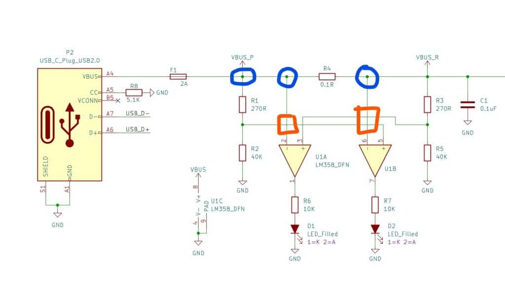
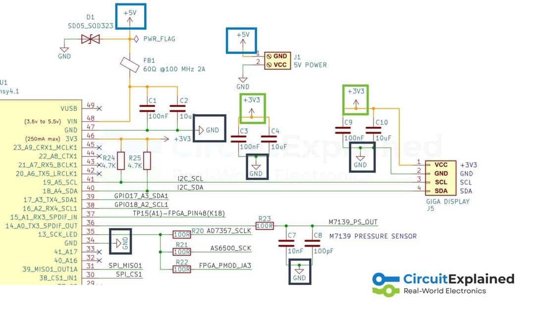
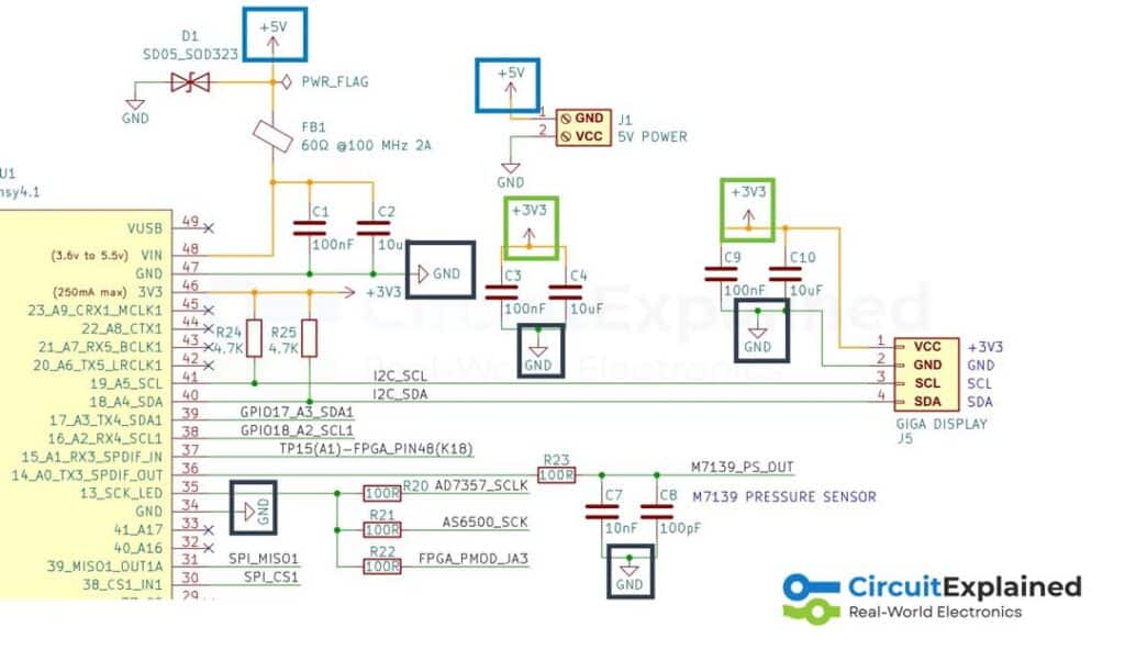
In the diagram above, the blue-circled points show junctions, which means the wires are connected at those locations.
The orange-highlighted areas show wires that simply cross each other — there is no electrical connection at those points.
Recognizing Power Nodes
Voltage nodes are single-terminal symbols used in schematics to show a specific voltage level, such as 5V, 3.3V, or GND.
When a component terminal is connected to a voltage node, it means that point in the circuit is fixed at that voltage. Voltage nodes are a special type of net label. Any terminals connected to the same voltage node name are electrically connected, even if no wire is drawn between them.
This helps keep schematics clean and easy to read, especially in larger circuits.
Voltage nodes with the same name, such as GND, 5V, or 3.3V are all electrically connected to each other, even if no wires are drawn between them.
The ground (GND) node is especially important because many components in a circuit need a connection to ground.
if you want to know more about the ground in electrical, we suggest the reading.
Final Thoughts
Reading circuit diagrams is not about memorizing symbols, it’s about understanding connections and current flow.
Start small, practice often, and don’t rush.
Once you understand schematics, electronics becomes much more enjoyable and powerful.
1 Comment