
What Is a 555 Timer?
When you learn about the basics of electronics, you often question yourself: “What is the 555 timer?”
As it is an IC, it creates highly stable time delays as well as pulses and oscillating frequencies for your circuit. The IC is famous as a 555 timer circuit for providing you with as many as three different types of mode operations. which are astable, monostable, and bistable.
IC has Astable as most frequently operated mode since it provides continuous wave output which doesn’t need to get triggered externally by the user of your circuit.
In the case where your interest develops over how this IC functions internally, then I suggest that IC 555 timer datasheet will be very helpful for you to get your hands on the pinout, internal working, and voltage limitations of the device.
What Is the Output of a 555 Timer?
A question all of you asking for the first time do get.
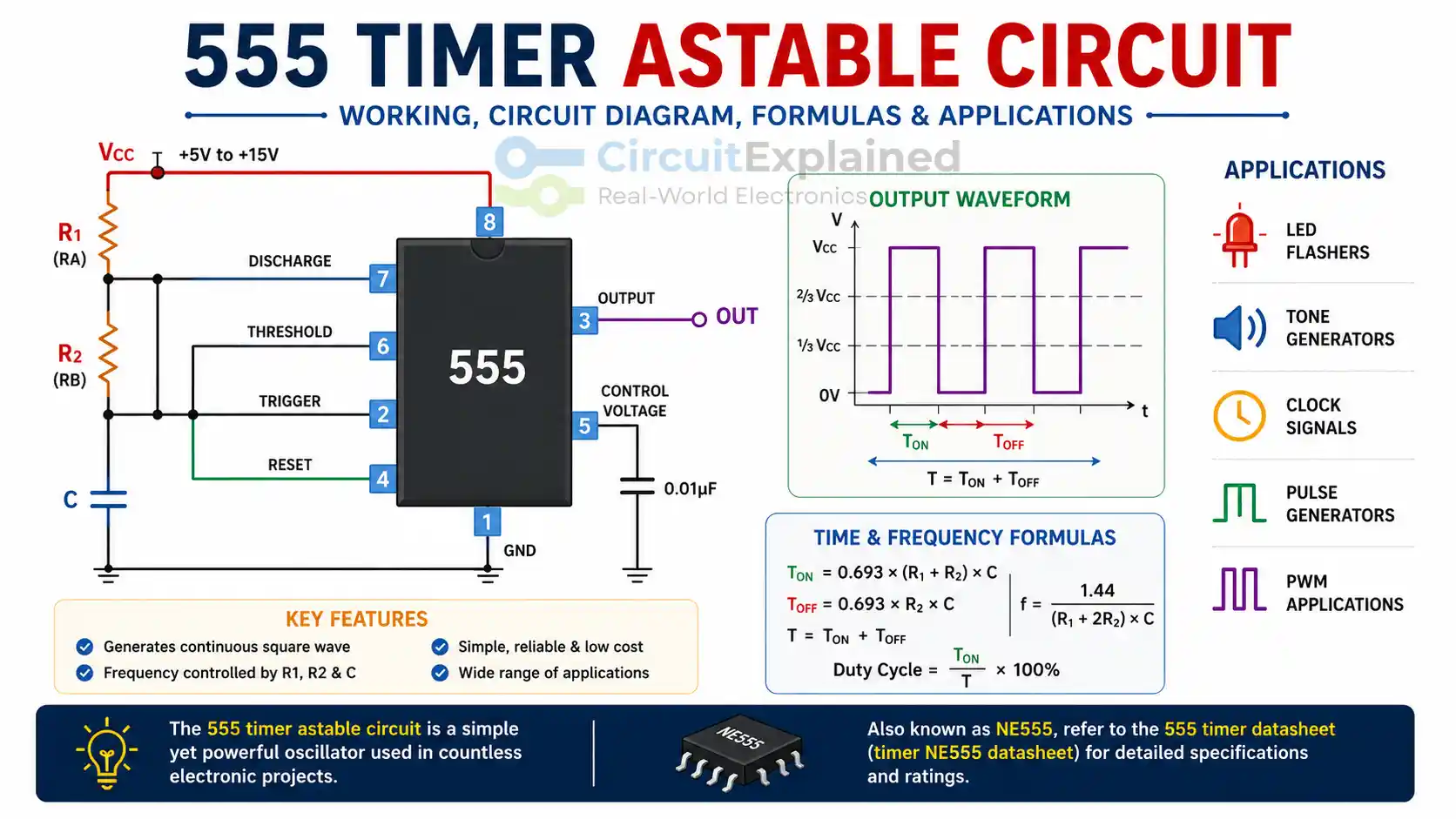
If the 555 timer is operating in astable mode, the output would be a continuous square waveform.
that is to say,
The signal flips between the high and low states. it won’t get stalled until the supply is on, and it won’t stop to get oscillations in between High and Low, the rate of flip between High and Low states depends on the resistors and the capacitor.
All of the qualities of this continuous pulse stream make the 555 timer a versatile device that can be used for creating tone generators, making LED flasher circuits, and generating clock signals.
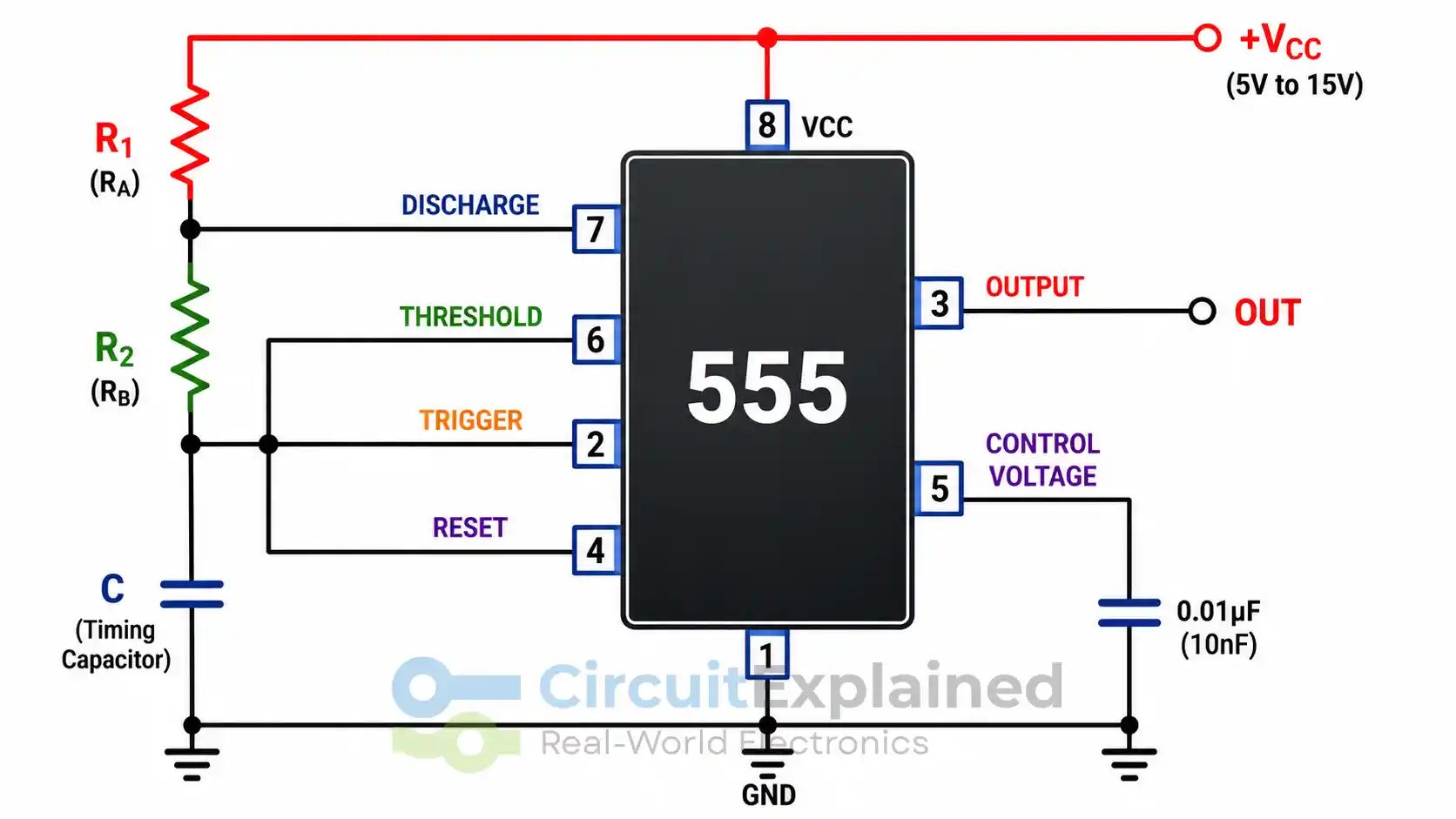
Understanding How the 555 Timer Astable Circuit Works
Continuous Oscillation
In a 555 timer circuit configured in astable mode, the capacitor charges and discharges continuously.
- Charging occurs through R1 and R2
- Discharging happens through R2 only
This process creates an endless loop, generating a square wave output.
Components Required
Basic Circuit Elements
To build a working astable circuit, you need:
- 555 Timer IC
- Two resistors (R1 and R2)
- One capacitor (C)
- Power supply
These components define the timing behavior of the circuit.
Timing Formulas for 555 Timer Circuit
Calculating Frequency and Output
The timing of the 555 timer circuit depends on simple formulas:
Time HIGH (TON)
TON = 0.693 × (R1 + R2) × C
Time LOW (TOFF)
TOFF = 0.693 × R2 × C
Total Time (T)
T = TON + TOFF
Frequency (f)
f = 1.44 / ((R1 + 2R2) × C)
You can verify these equations in any standard 555 timer datasheet or timer NE555 datasheet.
Duty Cycle in Astable Mode
Understanding Output Ratio
The duty cycle tells you how long the signal stays HIGH compared to the full cycle.
Duty Cycle = (TON / T) × 100
In a typical 555 timer circuit, the duty cycle is greater than 50% because charging takes longer than discharging.
Applications of 555 Timer Astable Circuit
Where It Is Used
The 555 timer remains widely used due to its flexibility. Common applications include:
- LED flashers
- Pulse generators
- Clock signals
- Tone generators
- PWM circuits
Because of its simplicity, it appears in both hobby projects and professional designs.
Why Engineers Still Use the 555 Timer
Key Advantages
- Low cost and easy availability
- Simple design and implementation
- Stable performance
- Wide operating voltage range
Even today, the 555 timer circuit continues to be a fundamental building block in electronics.
Conclusion
The 555 timer astable circuit offers a simple yet powerful way to generate continuous square wave signals. If you understand what is a 555 timer and what is the output of a 555 timer, you can design a wide range of practical circuits.
By referring to the 555 timer datasheet, you can fine-tune your design and achieve accurate timing. Whether you are a beginner or an experienced engineer, mastering this circuit opens the door to countless electronic applications.